In applications such as new energy, industrial measurement and control, motor testing, and energy storage inverters, the quality of current signal acquisition directly determines the control reliability and data credibility of the entire system. Many equipment selection processes focus solely on range while overlooking key parameter details, which can later lead to measurement deviations, data drift under varying operating conditions, and long-term zero-point offset. By understanding the four core specifications of the current sensor , you can quickly assess whether a product is suitable for the specific site conditions—and this serves as the most critical reference when evaluating selection options from manufacturers of current sensors, as well as from .
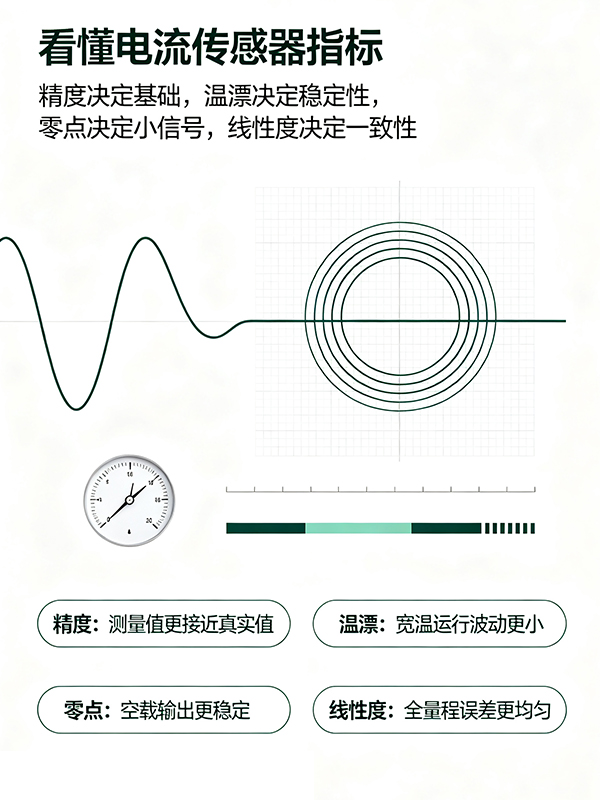
Accuracy: the fundamental scale of the measurement result
accuracy represents the error range between the sensor’s measured value and the true current, and it is the metric that everyone pays attention to first.
has the same nominal accuracy, but it’s important to distinguish between full-scale accuracy and reading accuracy, as the two differ significantly. Full-scale error means that even in the low-current range, the maximum error remains constant; in contrast, reading error varies in tandem with the measured current, performing better when measuring small signals.
Many field failures stem from selecting instruments based solely on accuracy figures while ignoring the operating range. For example, using a high-range sensor to measure small currents can lead to significant relative errors, even if the nominal accuracy appears high. When choosing a current sensor, it’s essential to consider the equipment’s typical operating current range, rather than simply pursuing higher accuracy numbers.
Temperature Drift: The hidden error caused by temperature variations
Industrial, automotive, and energy storage devices operate over a wide temperature range, from low-temperature start-up to prolonged full-load heating, with ambient temperatures constantly fluctuating. Temperature drift refers to the additional deviation in sensor output that occurs when the temperature changes.
Temperature drift is divided into gain temperature drift and zero-point temperature drift, and it is the most troublesome metric in high-precision testing scenarios. Ordinary sensors, under conditions with large temperature differences, experience readings that shift whenever the temperature changes, requiring the system to undergo repeated calibration. Low-temperature-drift current sensors can maintain stable measurements across a wide temperature range, significantly reducing on-site maintenance and the costs associated with frequent recalibration.
If your device requires high-low temperature cycling tests or long-term outdoor operation, the temperature drift specification takes precedence—even over static accuracy.
Zero point: the reference output when no current is input
Zero point (zero offset) is the sensor’s output value when the measured current is 0.
Ideally, the zero-current input and output should be zero, but in practice, the device, magnetic circuit, and circuitry all introduce an inherent zero-point offset. While this may have little impact during short-term use, over long-term continuous operation and under temperature fluctuations, the zero point will drift slowly. If the zero point is too large, during small-current detection, the signal can be masked by the zero bias, leading to misjudgments.
In applications such as motor test benches and weak leakage current monitoring, zero-point stability is particularly critical. High-quality current sensor manufacturers perform zero-point calibration at the factory and optimize magnetic shielding designs to reduce the influence of external magnetic fields on the zero point, ensuring baseline stability under no-load conditions.
Linearity: Ensures measurement consistency across the entire range
Linearity describes the degree to which the sensor’s output signal deviates from an ideal straight line relative to the input current.
products with poor linearity exhibit inconsistent error magnitudes at different points across the measurement range. They may measure very accurately in the middle of the range, but the deviation suddenly increases near the upper or lower limits. System calibration can only correct single-point errors and cannot compensate for nonlinearity over the entire measurement range.
Good linearity means that measurement errors are uniformly controllable across the entire range, from very small currents to full scale, making it suitable for applications requiring full-scale acquisition and large dynamic current variations, such as variable-frequency motors, bidirectional converters, and power battery testing.
Selection Summary
accuracy determines the baseline measurement level, temperature drift affects stability under wide-temperature operating conditions, zero-point performance ensures small-signal detection, and linearity dictates consistency across the entire measurement range. These four parameters constrain one another; it is not sufficient to evaluate only a single metric in isolation. When selecting an current sensor, or an , you must conduct a comprehensive assessment based on your specific operating conditions, temperature range, and current range—rather than simply comparing numerical values from datasheets. Reputable current-sensor manufacturers will take into account the customer’s actual field application scenario and provide guidance on how to balance these performance metrics, instead of unilaterally recommending the highest‑specification model.