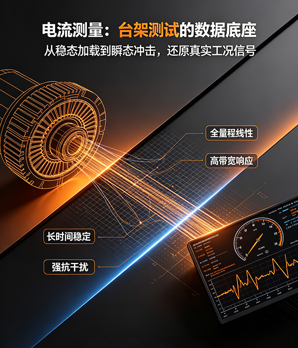
New energy motor development, performance calibration, and durability validation heavily rely on motor test bench systems. The current and voltage data acquired on the test bench directly determine the motor efficiency MAP, torque characteristics, temperature rise assessment, and control strategy iterations. Within the entire testing workflow, the current signal serves as the core carrier of energy and operating conditions; thus, the accuracy, bandwidth, and stability of motor test current measurement often constitute a critical factor in ensuring the credibility of the entire test bench dataset.
motor test benches operate under complex conditions, not just steady-state single loads. The testing process encompasses various operating scenarios, including steady-state loading, dynamic step changes, speed sweeps, impact loads, and high-speed weak-field operation, with current waveforms containing harmonics, transient spikes, and high-frequency components. Conventional measurement approaches can only capture average values, making it difficult to reconstruct the true transient current variations, which leads to deviations in efficiency calculations and distortions in dynamic characteristics, directly affecting motor calibration results. Therefore, for test bench current measurements, it is not enough to consider only the measurement range; evaluation criteria must be established from multiple dimensions.
1. Maintains high accuracy over a wide range, balancing both small and large current measurements
Motor test bench covers an extremely wide range: no-load low current, rated operating current, and short-term peak current all switch within the same system. Many sensors maintain acceptable accuracy near full scale, but their errors become significantly amplified in the low-current range, leading to distortion at light-load efficiency points.
High-quality measurement solutions require maintaining low measurement error across the entire range, with good linearity even in the low-current region, ensuring data consistency under all operating conditions—no-load, light-load, rated, and peak—thus guaranteeing full-range current accuracy on motor test benches and enabling true, reliable motor efficiency MAP testing.
2. Sufficient bandwidth to capture transients and harmonic components
The motor controller output is a PWM-modulated waveform, superimposed with switching-frequency harmonics and current transient pulses caused by load transients. When the bandwidth is insufficient, the sensor smooths out high-frequency details, making it impossible to reconstruct the true current waveform.
In dynamic testing, torque transient response, and controller harmonic analysis scenarios, the sensor must meet the test bench’s bandwidth requirements, fully reproduce high-frequency current details, satisfy the motor test bench’s transient current acquisition and motor controller harmonic measurement needs, and support fine-grained analysis of motor control algorithms and loss characteristics.
3. Excellent temperature drift and long-term stability, suitable for extended durability testing
Motor test bench durability tests often run continuously for dozens or even hundreds of hours, during which ambient temperature and the motor’s own temperature rise both change steadily. Sensors with large temperature drift will accumulate gradual offsets as temperature varies; data that was properly calibrated at the outset will drift after prolonged testing, leading to inconsistencies between early and later test results and increasing the cost of repeat testing.
low-temperature-drift current sensors ensure stable measurement results during current monitoring in motor durability tests, reduce downtime caused by frequent calibration, and improve test bench efficiency.
4. Isolation and anti-interference capability, suitable for complex electromagnetic environments
motor test bench integrates an inverter, a high-power power supply, and power cables, with strong electromagnetic interference on site. If the measurement equipment lacks sufficient isolation performance, it can easily introduce common-mode interference, causing waveform superposition noise and resulting in data jitter.
Reliable electrical isolation and anti-interference design enables isolated measurement for high-power motor testing, suppresses common-mode noise generated by high-power circuits, ensures that weak-signal acquisition is not affected by power circuit interference, and safeguards both equipment and personal safety.
5. Signal output matches the data acquisition system, ensuring link fidelity
The output signal of the sensor must be compatible with the backend electric-drive test bench data acquisition system. Whether the output is an analog signal or a digital interface, distortion and noise in the signal chain will be superimposed on the original current signal. Ensuring signal fidelity starting from the sensor’s output end is essential to prevent introducing additional errors into the backend acquisition, despite precise front-end measurements.
Conclusion
The essence of motor test bench testing is to reconstruct the motor’s actual operating conditions through precise measurements. Voltage and current serve as the fundamental inputs for calculating power, losses, and efficiency; thus, the performance ceiling of the sensors determines the upper limit of the entire test bench’s data.
Select the one that matches the test bench scenario.High-precision current and voltage sensorIt not only meets basic reading requirements but also provides a reliable data foundation for new‑energy motor calibration testing, performance optimization, and durability validation, helping motor R&D teams efficiently complete product iterations while offering a trustworthy measurement solution for motor test‑bench system integration and electric‑drive performance testing.